Plan depiction
Representation levels
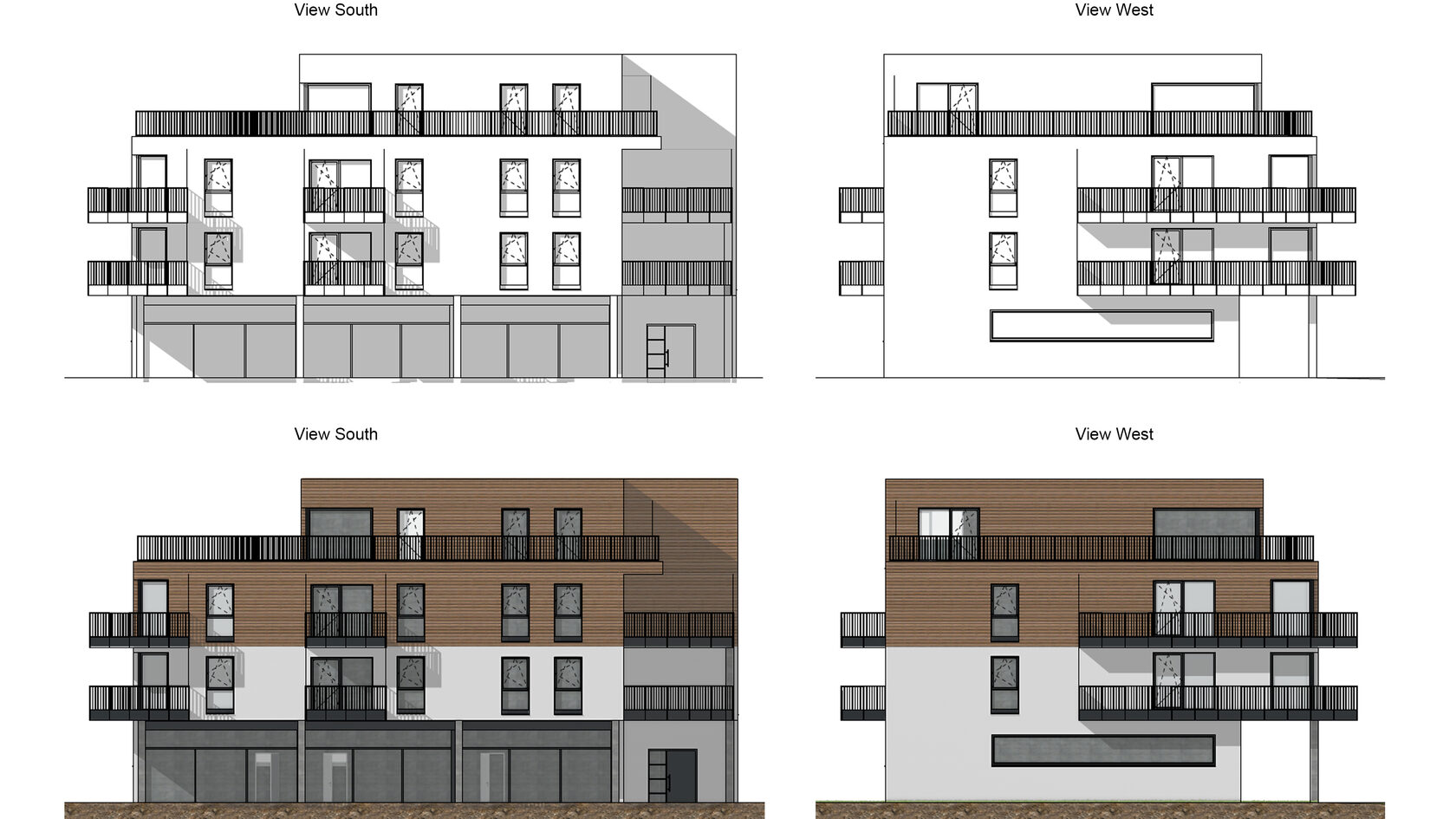
Plans are depicted depending on the scale, based on country-specific standards (ÖNORM, DIN, SIA) or on individual settings. Of course you have the option to transfer changes in a planning stage to other planning stages.
The scale and depiction of all parametrical construction objects and 3D free forms can be managed automatically with representation levels (level of detail of the planning). The definition of a representation level is graphic-based and is therefore easily and quickly adapted to individual requirements.

In design planning a number of details are not yet set. The depiction of floor plans, facade views and sections takes place in a reduced form. This also applies for dimensioning, labelling and hatches. With delivery of ELITECAD the country-specific standard is preset.
The depiction in work drawings
The depiction in work drawings is carried out in a higher level of detail. Multi-layered depictions with appropriate materials, a precise, associative labelling and the definition of connection details are obvious. Graphical means like arbitrary hatches, types of lines, fonts, colours etc. support your individual depiction.
Work drawings remain of course assigned to the model and other planning stages can be derived from it, so that your project status always remains consistent and up-to-date.
In detail planning construction details are specified based on the work drawing and have an increased level of detail. The extensive library of building components and symbols helps you to work out the details, which can remain associated with the model or being decoupled. As a result the independent 2D processing of details is possible.

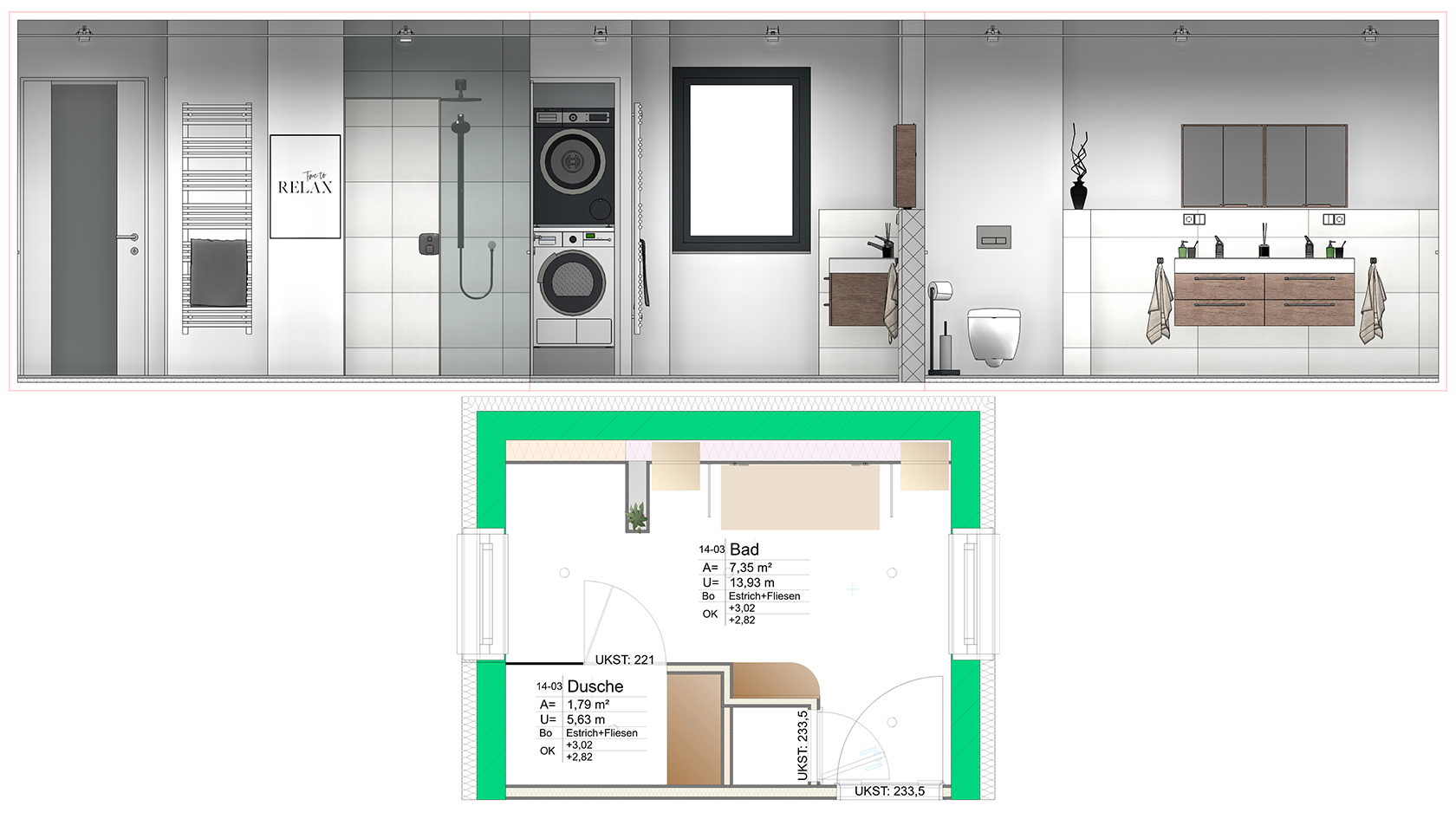
Automatic elevation views
Would you like to show all the walls of a room or facades next to each other in the views? The automatic elevation view is the perfect tool for this. What used to be possible with many manual intermediate steps is now possible with just a few clicks. And if something changes afterwards, all changes are automatically updated.

Coloured plan depiction: attribute visualisation
In ELITECAD data and information of objects or the entire model is stored in attributes. On the one hand, these attributes are essential for data exchange with other applications, on the other hand they are also a valuable source of information for plan depiction. The graphical representation of attributes as well as the visualisation of certain object properties in ELITECAD enables a large number of applications. The visualisation of information is always easier to interpret than a list or a table.
For instance: information about storey, fire rating, room and apartment groups or the construction progress can be ideally depicted with this tool. The possibilities are endless, because any kind of information, generated automatically by the program or manually created by the user, can be used as a basis to depict information. Even user-defined attributes or IFC properties can be displayed. Another area of application is searching for certain objects, which feature a certain attribute, independent of its value (for instance, all objects that have an article number), or vice-versa the depiction of objects in a certain colour which lack the given attribute. Of course, the coloured depiction can be printed as well.
The 3D transparency options for views were therefore created for a better overview. Control views are also of practical use, where objects whose attribute values are shown in colour according to certain rules and those objects that contradict these rules are shown in red, for example. This way you can see all the errors in the attributes at a glance.
Rules and value ranges for attribute colours are created quickly and offer numerous options for reducing the colours to be defined to a small number.
Plans with up-to-date information: attribute label
Nowadays, the process of building modelling mostly concerns 3D and BIM models, nevertheless 2D plans are still a major part of the planning and release process. They provide valuable information, which has to be detailed but structured clearly and always needs to be up-to-date.
In ELITECAD, this task is solved efficiently and automatically by the attribute label function. Every attribute label is linked to a certain object, which provides the information. Instead of plain text in the drawing, the plan depiction of the attribute label automatically updates if any changes occur to the main object. For instance, if the thermal transmittance value of a parametric wall objects changes, the plan depiction changes accordingly. This type of graphical representation of information can be configured with user-defined templates.
The parametric labelling of rooms in sections is now possible via a new attribute label. Select the desired rooms with just one click in the section and place the label at the appropriate position. Displayed information such as floor layers, room name or room height can of course be freely configured and, as usual in ELITECAD, are automatically adjusted in the event of changes.
Same but different: plan variants
The easiest way to create a variant of a plan in ELITECAD is to use the copy function of views. The function works independently of the view type, even entire plot views with referenced views can be copied. By copying views, it is ensured that certain parameters, like the view direction onto the model in the copy are identical to the original. That way, the same scene can be used for different light settings, for instance daylight and night time. Generating views with different content is easy as well. Simply change the content by manipulating the layer filter of the copy – job done!

